BDMP Input Format
The BDMP language
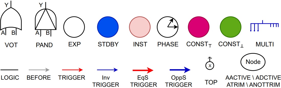
This section describes the BDMP language as originally described by Bouissou and Bon in 1 and that has been extended over the years with various elements. BDMPs are rooted directed graphs whose leafs represent the failure of elementary components. Syntactically, BDMPs extend SFTs by a PAND gate, various types of leaves and four types of triggers. Semantically, BDMPs introduce two new predicates alongside the failure predicate of SFTs: (1) activation predicate and (2) trimming predicate. From an activation point of view, each element of a BDMP can be in either of its two mutually exclusive modes: (1) activation and (2) deactivation. We show the most commonly used elements of the BDMP formalism in Figure 1 and discuss these elements here:
Gates
The first two elements in the first row of Figure 1 are BDMP gates. The first gate is a VOT, and it is a static gate. It has two associated parameters: (1) K and (2) N. We write it as VOT(K,N). Its output has a value 1 (denoting a failure) if and only if at least K inputs have the value 1. The AND and OR are special cases of VOT with K=N and K=1. That is, AND (OR) fails upon the failure of all (any) of its inputs and repairs upon the repair of any (all) of its inputs. The second gate in Figure 1 is a PAND, and it is a dynamic gate. PAND has two variants in the literature: (1) exclusive (PAND<), and (2) inclusive (PAND≤). The former (PAND<) fails when its second input fails while the first input is failed. (A failure of the second input before the failure of the first input leads the PAND< to a fail-safe state until some repair occurs.) The latter (PAND≤) also considers the simultaneous failure of its inputs as a failure. The repair behaviour of PAND leads to four variants: (1) repair first, (2) repair second, (3) repair any, and (4) repair all. That is, the PAND repairs upon the repair of either its left (first) input, right (second) input, any of its inputs, or all of its inputs. These repair behaviours of PAND are not common among the other fault tree extensions as BDMPs are the first ones to reflect on them. Since the BDMP formalism and EDF tools consider only PAND< behaviour, this paper only provides the semantics of PAND<. Henceforth, we use PAND to represent PAND<.
Leaves
BDMP leaves failure behaviour depends on their activation status. All but the first two elements of the first row in Figure 1 are the leaves of BDMPs. Leaves are associated with the probability distributions that govern failure modes of physical components, and the type of a leaf implicitly restricts the kind of associable distributions. The first leaf is exponential type (EXP). It can only fail in its active mode. Its failure behaviour follows an exponential probability distribution with rate λ ∈ ℝ> 0. The repair behaviour of EXP follows an exponential distribution with rate~μ ∈ ℝ>0 and is independent of its activation status. The standby type leaf (STDBY) has two associated but mutually exclusive failure modes: (1) active and (2) standby. STDBY can fail both in the activated and deactivated modes, but with two different rates: (1) standby failure rate (λs), and (2) active failure rate (λa). STDBY repair behaviour follows an exponential probability distribution with rate μ ∈ ℝ> 0, and its repair behaviour is independent of its activation status. The instantaneous type leaf (INST) represents component failures that follow the Bernoulli probability distribution; it models on-demand failures with parameter γ∈[0,1]. An INST does (does not) fail with probability γ (1-γ) upon activation. The repair behaviour of INST follows an exponential distribution with rate μ ∈ ℝ> 0. The phase type leaf (PHASE) does not model failure modes of components; it enables BDMPs to model the phase-type mission profiles. The failure (repair) of PHASE is interpreted as the start (end) of a phase. PHASE fails (starts) with probability one upon activation. This behaviour makes it easy to represent a succession of phases, by linking each phase to the next one by a standard trigger. The repair (end) of PHASE follows an exponential distribution with rate μ ∈ ℝ> 0. CONSTfail (CONSTfailsafe) represents house-type events, i.e., they remain constantly fail (fail-safe) throughout the analysis. The multi type leaf (MULTI) represents a batch of independent and identical EXP{}s. MULTI has three important parameters of interest: (1) the number of components n, (2) minimum required components m, and (3) the number of repairmen p≤n. MULTI fails when n-m+1 of its components fail.
Connecting links
All but the last two elements in the second row of Figure 1 are the connecting links. These are the edges connecting two nodes in the underlying graph of a BDMP. Let o (t) denote the origin (target) of the connecting link and p1, ... , pn denote the predecessors of t. Then the first element is logic-type link (LOGIC). It propagates activation, failure and trimming among BDMP elements. The second element is before{}-type link (BEFORE) connecting two INST{}s. It imposes an order on their test. That is, if o and t are activated simultaneously, then o is tested before t. The following four elements are triggers which control the activation mechanism in a BDMP: (1) standard trigger (TRIGGER), (2) inverted trigger (INVTRIGGER), (3) equal to source trigger (EQSTRIGGER), and (4) opposite to source trigger (OPPSTRIGGER). TRIGGER activates t as soon as o fails and at least one pi is active. INVTRIGGER activates t when o is not failed and at least one pi is active. EQSTRIGGER disregards the activation status of pis, and it activates t as soon as o has failed. OPPSTRIGGER disregards the activation status of pis, and it activates t while o is not failed.
Miscellaneous
The last two elements in the second row of Figure 1 are miscellaneous type elements. The first element represents the top event (TOP); it follows its unique successor's failure and repair behaviour. The second element represents four types of flags: always deactivated (ADACTIVE), always active AACTIVE, always trimmed ATRIM and always not trimmed ANOTRIM. These flags can control the activation and trimming status of any BDMP node. If the AACTIVE (ADACTIVE) flag is true, then the node remains constantly active (inactive). Likewise, If the ATRIM (ANOTRIM) flag is true, then the node remains constantly trimmed (not-trimmed).
Syntactically admissible BDMPs
The BDMP syntax is a quite flexible in terms of the arrangement of elements. The topology of its LOGIC links must respect the usual constraints for fault trees. As for triggers, there are three syntactic restrictions: (1) a trigger must not have TOP as its target, (2) the source and the target of a trigger must not be the same, and (3) two triggers must not have the same node as their target. Note that ``cycles'' using triggers may exist; e.g., a trigger from u to v may co-exist to a trigger from v to u. We impose no additional syntactic restrictions on BDMPs and assume that BDMP adhere to the above three (standard) constraints.
Running example
We adopt a BDMP benchmark from 2 as a running example. This benchmark is a simple electric power supply (SEPS) with cascade redundancies which is a scaled-down version of an emergency power supply used to power the safety instrumentation of a nuclear power plant. The purpose of SEPS is to continuously provide power to the BusBar which feeds the safety instrumentation. We first discuss the schematic of SEPS and then provide its BDMP.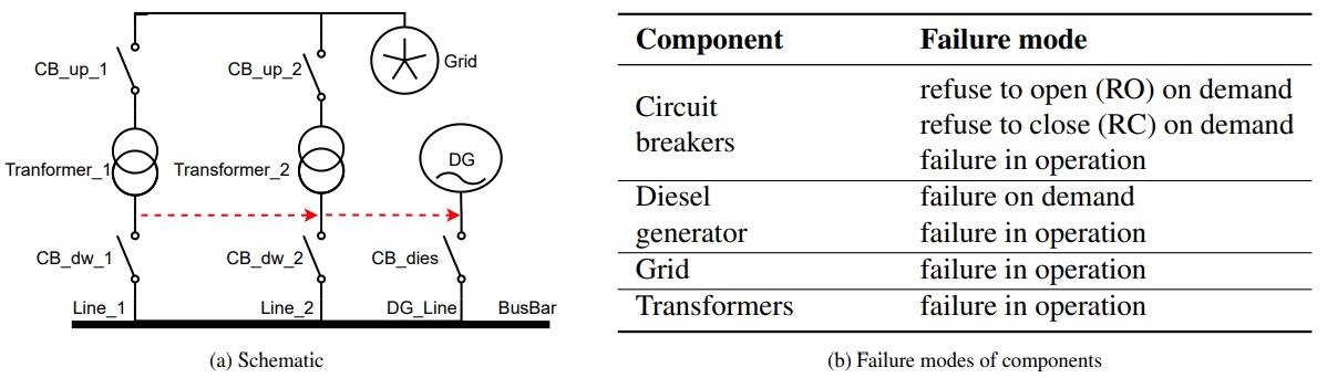
Schematic
Figure 2a depicts the schematic of SEPS. The BusBar is initially powered by Grid through Line_1. If Line_1 fails, then the Busbar is powered by Grid through Line_2. The failure of Line_2 switches the Busbar load to the diesel generator, i.e., DG_line. This reconfiguration strategy, highlighted by red colour arrows, is achieved through the opening and closing of circuit breakers. For instance, assume that Busbar is powered by the Line_1 and Transformer_1 fails, then the two circuit breakers (CB_up_1 and CB_dw_1) of Line_1 must open, and the two circuit breakers of the Line_2 (CB_up_2 and CB_dw_2) must close to achieve the successful reconfiguration. All components are repairable; the repair of components executes the reconfiguration strategy in reverse.
Failure modes
The failure modes of each component are provided in Figure 2b. The circuit breakers can fail in different operating modes: normal operation, opening, and closing. The diesel generator (DG) also has an on-demand failure mode, i.e., it can fail while switching the load to the DG_Line. All failures in operation follow an exponential distributions with rate λ=10-4. All failures on demand follow Bernoulli distributions with probability γ=10-4. All repairs follow an exponential distribution with the rate μ=10-1.
BDMP
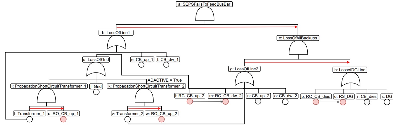
The BDMP for the SEPS benchmark is provided in Figure 3. This BDMP extends the one provided in 1 by including the propagation of transformers' short circuit towards Grid. Two BEFORE links are also included. We obtained this BDMP from an online BDMP repository provided by EDF . The TOP for this BDMP is an AND (notice the symbol of and gate), and it represents the event when SEPS fails to feed power to the BusBar. Given the understanding of the system schematic, we can intuitively explain the behaviour of BDMP. For instance, initially LossOfLine1 (notice the symbol of an or gate) and its successors except PropagationShortCiruitTrasformer_2 (notice the ADACTIVE flag) are active. The failure of Transformer_1 activates RO_CB_up_1 and thus causes testing of its associated Bernoulli trial. The failure of LossOfLine1 activates LossOfAllBackups which in turn activates LossOfLine2. Any repair of trigger origin will deactivate the trigger's target; thus, executing the reconfiguration strategy in reverse. The true ADACTIVE flag will keep PropagationShortCircuitTransformer_2 and RO_CB_up_2 deactivated thoughout the BDMP analysis. However, Transformer_2 will be activated upon activation of LossOfLine2. This BDMP is a quite interesting test case as it has failures with multiple effects (the Grid), simultaneous and sequential activation of elements, two BEFORE links ((j,m) and (p,q)) and it models a real-world case study. Observe that k, w and their associated connecting links can be removed from this BDMP without affecting the dependability measures. We avoid any simplifications in this paper because our focus is a comprehensible semantics.
| Element | Type Syntax; |
|---|---|
| TOP | toplevel <name>; |
| AND | <name> and <input1> <input2> . . . <inputN>; |
| VOT | <name> xofy <input1> <input2> . . . <inputN>; where x, y ∈ N s.t. y=N and x ≤ y. |
| PAND< | <name> pand-excl-rep_x <input1> <input2>; where x ∈ {all, any, f irst, second}. |
| EXP | <name> exp lambda=<value> mu=<value>; |
| STDBY | <name> stdby lambda_a=<value> lambda_s=<value> mu=<value>; |
| INST | <name> inst gamma=<value> mu=<value>; |
| PHASE | <name> phase mu=<value> in progress=<bool>; |
| MULTI | <name> multi lambda=<value> mu=<value> nr_items=<value> nr_ok=<value> min required=<value> nr repairmen=<value> |
| CONST⊤ | <name> given_fail |
| CONST⊥ | <name> fail_safe |
| TRIG | trigger <source name> <target name> |
| InvTRIG | inverted trigger <source name> <target name> |
| EqSTRIG | equal_s_trigger <source name> <target name> |
| OppSTRIG | inverted_s_trigger <source name> <target name> |
| BEFORE | before <source name> <target name> |
| AACTIVE | always_active <name> |
| ADACTIVE | always_deactive <name> |
| ATRIM | always_trim <name> |
| ANOTTRIM | always_ntrim <name> |
Galileo syntax extension for BDMPs
BDMP models are textually defined in Figaro format, which is quite verbose and manually intractable. Although KB3 provides graphical means to model a BDMP and to export the BDMP model in the Figaro format, it is neither open source nor publicly available. Tool developers interested only in the structure of a BDMP may not have access to (or may not want to use) the KB3 and Figaro knowledge base details. Therefore, we propose a simple language for manual modelling of BDMPs by extending Galileo, a syntax originally proposed for DFTs 2,3, to BDMPs. Many DFT analysis tools including STORM 4 support this language. Table 1 presents the Galileo-based syntax for BDMPs, where:
- <name>, <source_name>, <target_name>, <input1>, <inputN> are strings;
- <value>∈ℝ≥0 is a valid non-negative real number; and
- < bool>∈𝔹 is a Boolean value.
- toplevel SEPSFailsToFeedBusBar ;
- SEPSFailsToFeedBusBar and LossOfLine1 LossOfAllBackups ;
- LossOfLine1 or Transformer_1 LossOfGrid CB_up_1 CB_dw_1 ;
- Primarylinefails or Grid_fails CB1_IO ;
- LossOfGrid exp lambda = 0.0001 mu=0.1 ;
- CB_up_1 exp lambda = 0.0001 mu=0.1 ;
- CB_dw_1 exp lambda = 0.0001 mu=0.1 ;
- Transformer_1 exp lambda =0.0001 mu=0.1 ;
- trigger LossOfLine1 LossOfAllBackups ;
As the BDMP of the running example is a bit large, we provide the Galileo description for the first two levels of the hierarchy; see Listing 1. The syntax starts with identifying the top-level event (TOP) and connecting all BDMP elements to it. The second row defines that TOP is an AND gate with two inputs which are defined in the next two rows. The next four rows define EXP type leaves, and the last row of Listing 1 provides the syntax of the trigger. The elements can be defined in an arbitrary order. Note that the Galileo description of the complete BDMP can be automatically generated from its Figaro-format definition using our tool implementation.
The Galileo format cannot be directly analysed using the EDF analysis tools (Yams and FigSeq) and Storm-Figaro as these tools use Figaro knowledge base descriptions as input. We have developed Python scripts that translate Galileo to KB3 input format so as to integrate the Galileo syntax with the existing EDF tool-chain. A Python script can also automatically translate any Figaro format BDMP model to Galileo format. Our semantics-based analysis tool (Bdmp2Gspn) supports the Galileo syntax.
References
- M. Bouissou, J.-L. Bon, A new formalism that combines advantages of fault-trees and Markov models: Boolean logic driven Markov processes, Reliability Engineering & System Safety 82 (2) (2003) 149–163. doi:10.1016/S0951-8320(03)00143-1. URL https://doi.org/10.1016/S0951-8320(03)00143-1
- K. J. Sullivan, J. B. Dugan, D. Coppit, The galileo fault tree analysis tool, in: Digest of Papers: FTCS-29, The Twenty-Ninth Annual International Symposium on Fault-Tolerant Computing, Madison, Wisconsin, USA, June 15-18, 1999, 1999, pp. 232–235. doi:10.1109/FTCS.1999.781056. URL https://doi.org/10.1109/FTCS.1999.781056
- J. B. Dugan, Galileo: A tool for dynamic fault tree analysis, in: B. R. Haverkort, H. C. Bohnenkamp, C. U. Smith (Eds.), Computer Performance Evaluation: Modelling Techniques and Tools, 11th International Conference, TOOLS 2000, Schaumburg, IL, USA, March 27-31, 2000, Proceedings, Vol. 1786 of Lecture Notes in Computer Science, Springer, 2000, pp. 328–331. doi:10.1007/3-540-46429-8_24. URL https://doi.org/10.1007/3-540-46429-8_24
- C. Hensel, S. Junges, J.-P. Katoen, T. Quatmann, M. Volk, The probabilistic model checker storm, CoRR abs/2002.07080. arXiv:2002.07080. URL https://arxiv.org/abs/2002.07080